
|

|

|
|
Applications > Environmental Management
|
|
|
|
|
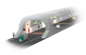
Expressway Tunnel Monitoring System
|

|
|
|
|
|
|

|
Introduction
|
This expressway tunnel monitoring system utilizes a distributed network control architecture, including Ethernet switches, a zone controller and a local controller. The ultra-compact and high cost-performance controller greatly simplifies system architecture and connection.
|
|
|
|
System Requirements
|
Tunnels can be classified into four categories by length: short tunnels (L<250m), middle long tunnels (250m<L<1000m), long tunnels (1000m<L<3000m) and super long tunnels (L>3000m). The longer the tunnel, the more monitoring devices are needed. According to the sub-systems, the tunnel monitoring system can be divided into: the lighting system, a ventilating system, traffic guidance system, CCTV system, fire alarm system, fire control system, emergency telephone system, broadcasting system, and additional tertiary tasks. The tunnel monitoring system can be classified into four groups by device: testing devices, controlling devices, display devices and communication devices. Testing devices include fire-alarm probes, vehicle detectors, COVI, visibility sensors, and wind sensors. Controlling devices include a traffic area controller, illuminated area controller, and ventilated area. Display devices include a computer workstation, large-scale monitor, and solar alarm. Finally the communication devices include switches, hubs, serial signal transmission equipment, optical transmitter and receiver.
|
|
Project Implementation
|
|
EKI-7659C
|
8+2G Combo Port Gigabit Managed Redundant Industrial Ethernet Switch
|
|
APAX-5343E
|
Power Supply for APAX Expansion Modules
|
|
APAX-5520KW
|
Micro PAC with XScale CPU
|
|
APAX-5017
|
12-ch Analog Input Module
|
|
APAX-5018
|
12-ch Thermocouple Input Module
|
|
APAX-5040
|
24-ch Digital Input Module
|
|
|
|
System Description
|
The zone controllers are used to collect information from field testing devices, process the information and send the information to the local control center. Control commands from the local control center are then sent to the zone controllers in order to directly control the corresponding devices. If the connection between the local control center and zone controllers is broken, the zone controllers can independently control field devices. Therefore, the zone controllers must be highly reliable. Advantech PAC is used as tunnel monitoring zone controller (APAX-5520KW). It supports backup functionality. Each controller offers serial port to communicate with other industrial devices. APAX high-performance I/O modules could meet signal processing commands of monitoring system. Every module is stacked and provides multiple functionality and program capacity, and is easy to detach and maintain.
|
|
Conclusion
|
APAX-5520KW can be simply used as the backup zone controller, concentrating on I/O process. In this way, it will not be disturbed by any other task and will achieve the most efficient and real-time control capability. APAX-5570XPE/5571XPE installed at central control room can process other tasks, such as HMI/SCADA, process, database, data log and communication with other systems. This architecture ensures system reliability, because APAX-5520KW could continuously implement I/O tasks without disturbing by other tasks running on APAX 5570XPE/5571XPE.
|
|
System Diagram
|
|
|
|
|
|